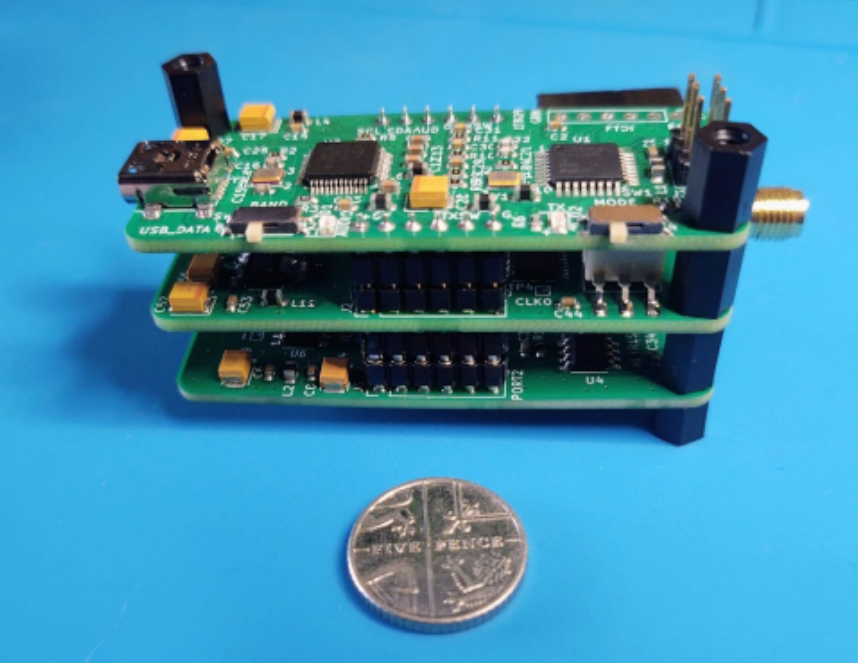
The TinyDX is a miniature FT8/4 QRP ~1W transceiver designed to be powered and operated via a USB connection to a smartphone/tablet running an FT8 app such as FT8TW for android or IFTX for IOS. It is able to operate on any 2 of the HF “high” bands, 20M, 17M 15M, 12M, 10M which are defined by the builder during the software configuration process. The TinyDx does not have CAT control but uses the transmit audio signal to switch the PA and receiver during the transmit/receive cycle. Band and mode are selected via 2 hardware switches on the main board.
Designer Barbaros (Barb) Asuroglu WB2CBA has shared the design on GitHub with all of the necessary fabrication files for the boards to be built and populated by the PCB manufacturer JLCPCB. The cost of having the boards built by JLCPCB is around £30 per set for an order quantity of 5 sets plus shipping. Choosing this option just leaves the individual to connect the pre-built boards together and load the bootloader and firmware as per the instructions on Barb’s blog.
To load the software the builder should be familiar with the Arduino IDE platform and the use of the Arduino UNO to install the bootloader and a USB to TTL adapter to load the software. For those with experience in this area it’s a simple enough task but for those who haven’t, it does present a bit of a learning curve as well as the additional cost for the programming devices ~£30.
As an alternative option to having the TinyDX factory built, I decided to embark on a trial hand build using unpopulated boards from JLCPCB and components from trusted sources such as Digikey and Mouser. I ordered 10 sets of PCBs and components with a view to offering the spares to anyone at my local club who might be interested in having a go themselves. Sourcing the right components turned out be quite a challenge as the part numbers supplied by Barb are specific to the JLCPCB parts library. I wasn’t fully aware of this until I finished the Tx board and started testing that I realised there was a major problem. I managed to trace the issue to excessive current draw on the supply to the VFO which turned out to be due to the wrong crystal type. Barb helpfully pointed out the error of my ways and pointed me to the searchable parts library on the JLCPCB website.
The TinyDX consists of 3 tiny PCBs that have been designed to be stacked and soldered together via 2 x 6 long pin headers. This approach makes it extremely difficult to separate the boards for any subsequent fault finding or rework. So for the trial build I used low profile turned pin headers and sockets to enable the boards to be easily separated. Most of the discrete components are 603 pitch which are probably the smallest sized components that can be soldered by hand. I adopted the approach of soldering each component in order of height starting with the ICs and then the discrete devices by type and value eg all of the 10k resistors, all of the 10nF capacitors etc thus slowly building up the boards with small groups of components. I found that that this approach helps to ensure that the right value components are placed in the correct locations. All of the components were soldered using a Lexivon LX-771 butane gas torch fitted with a catalytic nozzle and low temperature solder paste.
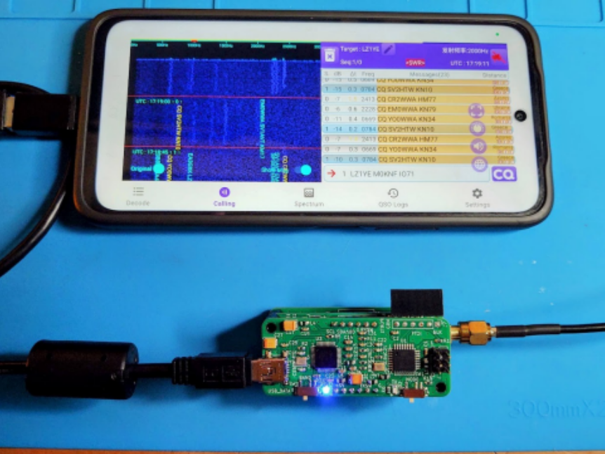
With all 3 boards completed and “sandwiched” together, initial testing commenced connecting the TinyDX via its USB connection to a PC running WSJTX. The TinyDX was identified as a USB sound card with power supplied to the transceiver via the same USB connection. A red LED on the board blinks briefly on start up to indicate that the AT328P microcontroller has initialised and a blue LED flashes to indicate when the sound card is being used by WSJTX. The receiver appeared to be working well with a clean signals displayed and decoded on WSJTX but, the TinyDX would not respond to tune or transmit commands.
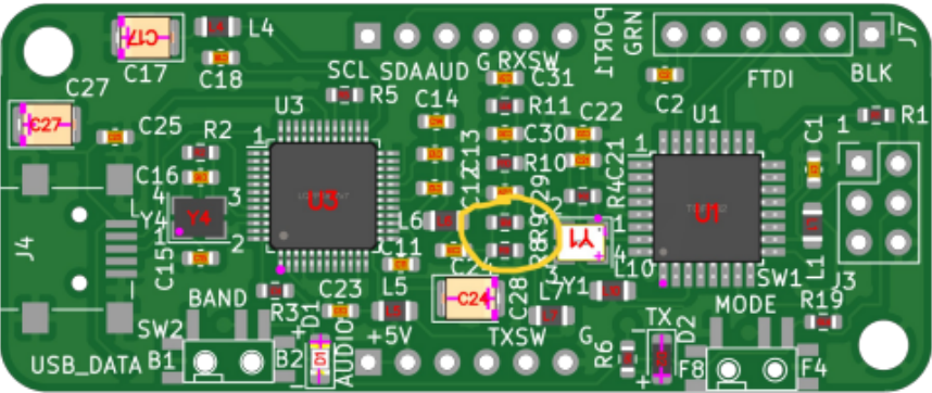
I was confident that the fault was not a design related issue so my thoughts turned towards workmanship or the possibility of another component selection error. To rule out workmanship issues I built a 2nd TinyDX and observed exactly the same problem of no transmit which at least gave me confidence that at least I had a repeatable build process. In the absence of any detailed summary of circuit operation I copied the TinyDX code into the Gemini AI platform. I had never used AI in this way before and was amazed at how well it was able to provide an overview of how each of the key hardware components and the code worked together. During my ongoing conversation with the AI “bot” it offered to produce a test script that could be used to test the TX switching routine through the Arduino IDE serial monitor. I accepted the offer and loaded the TinyDX with the AI generated code, enabling me to trace the fault to the voltage bias level on the Tx switching signal being too high. So, after rechecking my components placing against the circuit diagram, I returned to the JLCPCB website and uploaded the fabrication files for the board to check the component placing for the factory build process and… Eureka! I could see that there was an error on the PCB’s silkscreen in that the locations for the 2 resistors that form the 10:1 voltage divider had been transposed.
With the resistors correctly placed and the Tx switch operating as expected I put the TinyDX into operation and was astonished to get a response to my first CQ call on 20M from an operator in Italy quickly followed by more QSOs into Eastern Europe.
For me the enjoyment is in the challenge of the build and the learning along the way, but there’s no doubt that the TinyDX offers the mobile operator the ultimate in convenience and portability for FT8 operations.
[COMMENT] by Dan, AF5W (ex-KH6UW organizer / operator of the K3J DXpedition). I’ve been reading recent discussions regarding our 2001 K3J expedition with interest and very hopeful that KH3 will be back on the air someday. I have received multiple requests (ok hundreds) for uploading the logs on LoTW, eQSL, QRZ etc. As much as […]
Here in Ohio, the weather is often unpredictable, with rapid shifts between seasons. We have a saying, “If you don’t like the weather, wait five minutes.” We often joke about experiencing all four seasons in one day—and occasionally twice before lunch. But we’re not alone. It seems like the weather across the United States has become more erratic—and severe.
Whether you live in Ohio, Florida, or Alaska, bad weather significantly impacts ham radio antennas by altering their resonance, increasing static noise, or causing structural damage. Moisture from rain or snow can cause erratic SWR, while wind and ice can cause antenna failure.
Protecting antennas from weather damage is essential for maintaining performance, longevity, and safety. Because antennas are often installed outdoors—on rooftops, towers, or poles—they are constantly exposed to environmental stress (and whatever mood the sky happens to be in that day). A well-protected antenna system requires attention to both mechanical durability and electrical integrity.
Moisture & Oxidation
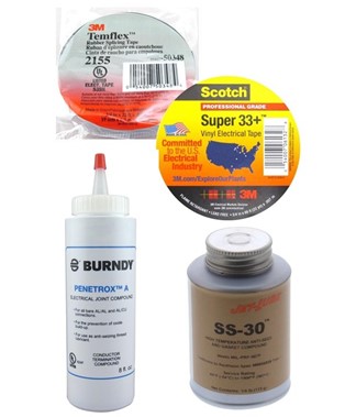
One of the primary concerns is moisture intrusion. Water can enter coaxial connectors, baluns, and feedlines, leading to corrosion and signal loss. Over time, even small amounts of moisture can significantly increase resistance and reduce efficiency—kind of like slowly turning your antenna into a very expensive, very ineffective resistor. To prevent this, all external connections should be sealed carefully. A common method involves wrapping connectors with a layer of Temflex 2155 rubber splicing tape, then a protective outer layer such as Scotch 33+ UV-resistant vinyl tape. This layered approach ensures both waterproofing and resistance to sunlight degradation.
Another critical factor is corrosion resistance. Dipole antennas are typically made from conductive materials like copper or aluminum, which can oxidize when exposed to air and moisture. While aluminum forms a protective oxide layer naturally, connections between dissimilar metals (such as copper wire and aluminum components) can cause galvanic corrosion—nature’s way of reminding you that not all metals get along. Using compatible materials or applying anti-oxidation compounds like Jet-Lube or Penetrox at junctions can mitigate this problem. Stainless steel hardware is often preferred for antenna fasteners and mounting because it resists rust and maintains structural integrity over time.
Devote the time to weatherproof external connections to block moisture intrusion and apply anti-oxidation compounds to prevent corrosion. (Image/DX Engineering)
Gone With the Wind
Wind presents a mechanical challenge, especially for longer antennas that span significant distances. Strong gusts can cause dipole antennas to sway, stretch, or even snap—sometimes with dramatic timing during a contest or net. To address this, proper tensioning is important. The antenna should be taut but not overly tight, allowing for some flexibility. Incorporating strain-relief elements, such as end insulators and support ropes made from UV-resistant synthetic materials (such as polyester), helps absorb some mechanical stress.
Additionally, pulleys and counterweights help support dipole antennas between trees, preventing wire breakage caused by wind-induced tree movement. A pulley—ideally stainless steel—is attached to the tree using a sturdy hook, with a rope running over it to hold a weight, keeping the wire taut while allowing it to move. Use just enough weight to keep the antenna from sagging, but not enough to audition for a suspension bridge. A plastic container filled with water or sand, or a 1- to 5-lb. piece of concrete or metal, usually does the trick.
A range of rope hardware kits are available at DX Engineering. Kits come with a combination of pulleys, shackles, rope clips, carabiners, thimbles, and more. The above kit includes two stainless metal pulleys for Mastrant 4-9mm rope. (Image/DX Engineering)
If a weight is impractical, consider using 2- to 3-foot marine-grade bungee cords. Rubber tarp straps are also a good choice. Those made with EPDM are rated to withstand sun exposure for 20 years or more. Storm door springs are another option—look for corrosion-resistant ones.
Antenna pulleys and counterweights. (Image/K8MSH)
Ice Cold
Ice and snow accumulation can add substantial weight to the antenna, increasing the risk of sagging or breakage. You’d think a small amount like a quarter inch of ice wouldn’t be much, but it can add approximately 100 to 500 pounds of weight to a single span of power line (depending on length). According to electric utilities, this significant weight can cause lines to sag or begin to snap. A half-inch layer of glaze ice acts as a massive overload, often exceeding power line design limits and causing them to break and cut power.
You can imagine what ice would do to an 80m dipole or sky loop—and it’s usually not good. Adapting antenna systems to colder climates is the best way to minimize damage. Designing the antenna with a gentle slope from the center toward the ends can help shed ice and snow more effectively, minimizing accumulation. An inverted-V with steep slopes would be an even better option. If you have the pulley system described in the preceding section, you could lower the ends until your antenna thaws—assuming you’re willing to venture outside to do it.
Other adaptations include using slightly thicker wire or stranded wire rather than solid wire to improve durability. Stranded wire is more flexible and less likely to fracture under load—because sometimes flexibility really is strength. Using 12- or 14-gauge stranded wire, along with heavier Dacron rope attached to the insulator, improves structural integrity.
Heat & UV
You’d think a sunny day wouldn’t be much of a threat to your antenna. But ultraviolet (UV) radiation from the sun can degrade many antenna materials over time, especially plastics—quietly and persistently, like a slow-motion failure you didn’t sign up for.
Coaxial cables and insulators are particularly vulnerable. To combat UV damage, it is important to use materials specifically rated for outdoor use. UV-resistant jackets on coaxial cables and UV-stabilized plastic insulators can significantly extend the lifespan of the antenna system. Regular inspection for cracking, fading, or brittleness is also important, as these are early signs of UV degradation.
Dark-colored or black ropes generally last longer in the sun because they have UV-stabilized pigments that absorb or reflect harmful rays, preventing them from breaking down the fiber. Polyester and polyethylene blends offer good UV resistance and strength while being lightweight. Also, most modern 550 paracord (Type III nylon) is UV-resistant, making it suitable for long-term outdoor use.
Keep an eye on traps, baluns, and common-mode chokes with plastic housings that are exposed to UV. Cracked plastic end caps or failed seals allow water inside. If this water freezes, it expands, causing the plastic or seal to split further. If you live in an area with summer temperatures in the triple digits, painting those plastic parts with white paint can help prevent meltdowns.
Antenna Mounts
Proper mounting and placement also contribute to weather protection. Positioning Yagi antennas away from trees can reduce the risk of damage from falling branches or abrasion from moving limbs during storms.
At the same time, the mounting structure itself must be robust enough to withstand environmental forces. Using guys for vertical antennas, taller masts, or towers can improve stability in high winds. Concrete bases for taller towers, made to the manufacturer’s specifications, provide the necessary stability and peace of mind when the wind picks up at 2 a.m.
When mounting antennas on roof tripods or securing masts to the house, anchor into roof rafters, not just decking or fascia, and waterproof at roof contact points with roofing sealant or pads. Add a guy wire kit for masts over 10 feet tall to provide extra stability. Use heavy-duty, rust-resistant fasteners, and maintain a minimum of 20 feet from power lines—because that’s one kind of contact you definitely don’t want to make.
I Have a Guy
Guying helps protect against environmental loads such as ice accumulation. In colder climates, ice can form on antennas and masts, adding significant weight. This extra load increases the structure’s stress and can lead to sagging or collapse if not properly supported—gravity is very consistent about this. Guy lines help bear this additional weight by sharing the load with the ground anchors, reducing the strain on the mast itself.
Rope guy lines are extensively used in antenna installations, particularly when non-conductive, lightweight, or flexible support is required. These are common in amateur radio and temporary setups. Rope is used to support the ends of dipoles or the center of inverted-V antennas, tying them to trees, masts, or ground anchors. Small to medium-sized vertical antennas and portable masts frequently use non-conductive rope guy lines to keep the antenna upright without interfering with the RF radiation pattern. Heavy-duty guy lines for towers are typically made of galvanized steel or other corrosion-resistant materials, such as Phillystran, to withstand long-term exposure to the elements. Both the rope and the heavy-duty guys must be properly tensioned—not too loose or too tight (the antenna equivalent of “just right”). Turnbuckles are often used to adjust tension on large towers precisely. The angle of the guy wires is also important; wider angles provide better lateral stability, while multiple evenly spaced wires ensure balanced support.
Phillystran High-Performance Tower and Antenna Guy Lines come in a range of diameters and break strengths. (Image/DX Engineering)
Shocking Experiences
Lightning and static buildup are additional hazards. Installing a proper grounding system is crucial. This includes grounding the antenna support structure and using a lightning arrestor in the feedline. The arrestor should be connected to a good earth ground, providing a path for excess voltage to dissipate safely—the shorter the path, the better. Disconnecting the antenna during severe storms is another simple but effective precaution. It’s better than learning about lightning the hard way.
Storm Checklist
Here are some suggestions to protect ham radio antennas before a storm:
Disconnect and ground all coax cables, preferably outside the home.
Lower temporary masts, wire antennas with pulleys, and crank-down antennas. Tighten guy lines as necessary on poles and towers.
Check feedline strain relief, drip loops, and connectors before snow/ice loading can happen.
Power up the station to confirm everything still works before bad weather—troubleshooting in a storm is never fun.
Have a simple, rapidly deployable antenna (e.g., an end-fed wire) prepared in a “go-kit” for immediate use after the storm, along with backup power (battery or generator).
Keep on Top of Things
Procrastinate and things will always get worse—antennas are especially good at proving this point. Routine maintenance, often overlooked, is essential for long-term reliability. Periodic inspections should include checking for loose connections, worn insulation, corrosion, and mechanical stress points. Any signs of damage should be addressed promptly to prevent further deterioration. Cleaning connectors and reapplying weatherproofing materials as needed can restore performance and extend service life.
Protecting your antenna from weather damage involves a combination of good materials, careful installation, and ongoing maintenance. Key strategies include sealing connections against moisture, preventing corrosion, ensuring mechanical stability against wind and ice, using UV-resistant components, accommodating temperature changes, and implementing proper grounding. By taking these steps, operators can ensure that their antennas remain reliable and efficient—even when the weather isn’t.
May is almost upon us with new DXpeditions taking place. The Featured DXpedition Timeline is now updated and available or next month – right side top (and now bottom). A first glance is below. NOTE: The timeline is updated regularly, dates of activities often change or can be tentative.
Takio Hata, JH3QFL informs DX-World that he will be active from Nuku’alofa, Tongatapu Island, Kingdom of Tonga, as A31AA from May 13 to 22, 2026. QRV on 80-6m; FT8. Bands: 80m to 6m. QSL Direct to JH3QFL or LoTW.
Yosuke, JJ1DQR (of DX-World Japan) let’s us know that he will be active from Male, Maldives as 8Q7QR during May 28 to June 1, 2026. QRV holiday-style; 160-6m. Participation in the CQ WPX CW contest. QSL via H/c (direct or buro).
The following is a press release from the Amateur Radio Software Award:
The Amateur Radio Software Award (ARSA) committee is proud to announce that the Hamlib project has been selected as the recipient of the 2026 Amateur Radio Software
Award. This year’s award honors the outstanding work of the current core developers:
Nate Bargmann (N0NB), George Baltz (N3GB), Daniele Forsi (IU5HKX), and Mikael
Nousiainen (OH3BHX).
The annual ARSA award recognizes software projects that enhance amateur radio and
promote innovation, freedom, and openness in amateur radio software development.
Hamlib was selected for its long‐standing and essential role in enabling software to
interface with transceivers and other controllable devices. For more than a quarter
century, Hamlib has provided a unified, reliable way to send control commands and read
device status. Despite its age, the project remains actively maintained, with new radios
and devices added regularly. Hamlib continues to be the go-to library for both
established and emerging amateur radio applications.
About Hamlib
Hamlib provides stable, flexible shared libraries that simplify the development of
amateur radio equipment control applications. Many modern transceivers include serial
(RS‐232, USB, etc.) or Ethernet/Wi‐Fi/Bluetooth interfaces that allow software‐based
control. Hamlib abstracts these interfaces, making it significantly easier for application
developers to interact with radios, rotators, amplifiers, and other controllable devices.
From WSJT‐X and Fldigi to JS8Call, Log4OM, and CQRlog, today’s widely used amateur
radio applications are built on Hamlib.
Nate Bargmann (N0NB) notes that “over the lifetime of the project there have been
several principal developers. Its founder is Frank Singleton, VK4FCS. Stéphane Fillod,
F8CFE, and until about a year ago Mike Black, W9MDB (SK), were successive principal
developers.”
Bargmann reports that the current long‐term support branch will receive the 4.7.1 release
in the coming weeks, adding support for new radio models and improving existing ones.
Work on Hamlib 5 is also underway. The new major version will introduce some
backward‐incompatible changes to isolate internal structures and align with modern
best practices, including breaking the C ABI. Discussions are ongoing regarding
potential API changes, and feedback from client developers is encouraged.
“There is no set date for a release of Hamlib 5.0.0,” Bargmann adds, “but hopefully
within the next year seems possible.”
To celebrate Hamlib’s selection as the 2026 award recipient—and to encourage
nominations for the 2027 Amateur Radio Software Award—the ARSA committee will
operate the special event station K7A from November 27 through December 7, 2026.
About the Amateur Radio Software Award
The Amateur Radio Software Award is an annual international award recognizing
software projects that enhance amateur radio and promote innovation, freedom, and
openness in amateur radio software development.
Award Committee
Claus Niesen, AE0S (since 2020)
Kun Lin, N7DMR (since 2020)
Rich Gordon, K0EB (since 2021)
Sebastian Delmont, KI2D (since 2026)
For nomination guidelines, event schedules, and information about past winners, visit https://arsaward.com.
Rikk, WE9G will be active from Borg, Iceland as TF/WE9G during May 10-19, 2026. Grid: HP94ob. QRV mostly on FT8 with some CW and SSB. QSO uploads to Club Log, QRZ, and LoTW will be real-time (and free) as usual. QSL via WE9G for direct/bureau and via VP9/WE9G for Club Log OQRS, QRZ, LoTW. * […]
[INFO by Jim, K0XV] – I am active via remote CW operation as A71AT from Doha, Qatar effective 2330Z 4/24/2026. All CW contacts are valid from this time and date. Following a very pleasant SSB QSO back on 4/22/26, I read that station A71AT control operator, Mohammed, operates remotely as he travels in Qatar. He […]
[GDXF SUPPORT] The VP0SG team would like to sincerely thank the German DX Foundation for their generous support of our South Georgia 2027 DXpedition with a financial contribution. This important support plays a key role in helping us move forward with the project and bring this rare DXCC entity on the air for the global […]