[REFRESH] – The Arctic Legends DXpedition team (RT9K) plan on activating the follow IOTA: — Chaichiy Island, EU-160 (as RI1PC) during July 4-7. — Vize Island, AS-055 (as RI0BW) during July 12-16. — Ugedineniya Island, AS-057 (as RI0BU) during July 18-21. — Isachenko Island, AS-050 (as RI0BI) during July 23-26. The journey will last 31 […]
Author: NA4DA
-
3B8 & 3B9/UR9IDX – Mauritius & Rodrigues
Continuing on from his recent FH (Mayotte) and FR (Reunion) activities, Ivan UR9IDX now has upcoming plans to be active from Mauritius (3B8) and Rodrigues (3B9). QRV on HF bands; CW & SSB. QSL info via CT9/UR9IDX address on QRZ; no LoTW.
-
Guide to May 2026 Ham Radio Contests—CW Edition
Today, OnAllBands turns its attention to Continuous Wave in celebration of the CQ WW WPX CW Contest at the end of May. We’ll get to that and other CW contests in a moment, but first let’s look at some of the reasons why this mode continues to captivate the amateur radio community:
- For newbies, it’s a fun and challenging mode to learn.
- For emergency operators, the dits and dahs of Morse code have a better chance of cutting through the noise compared to SSB in challenging conditions. Narrow bandwidths allow for efficient filtering of noise and other signals.
- For experienced operators, there’s nothing more exciting than managing a CW pileup, running a frequency in a contest, or challenging yourself to reach higher WPM speeds.
- For QRP enthusiasts, low power and CW go together like PEPs and carriers (or peas and carrots, if you’re into the whole vegetable analogy thing).
- For all hams, it’s a way to connect to the early days and traditions of telegraphy.
- For the international community of operators, use of Q codes and standardized abbreviations shatter global language barriers, making Morse code messages universally understood.
- For collectors, mechanical design enthusiasts, and results-driven contesters, it’s a chance to equip your shack or portable station with some of the coolest, precision-made gear in all of ham radio (see below for gear available at DX Engineering).
***
Plus, there’s no shortage of online CW groups and contesting opportunities. Here are a few:
The Straight Key Century Club sponsors a Monthly Weekend Sprintathon. The next one is scheduled for May 9, 1200Z to May 10, 2400Z. This event “aims to bring together operators with different skill levels in a regularly scheduled, informal operating event lasting 36 hours,” per the SKCC website. The SKCC was established in 2006 and is going strong with more than 29,000 members. Check out its website for useful resources, including the “SKCC Beginner’s Corner.”

(Image/SKCC) K1USN Slow Speed Test: This is held every Friday and Monday “for those who prefer a more leisurely CW pace or are new CW operators or contesters,” according to the K1USN SST website. If you copy under 25 words per minute and are looking for a less stressful place on the air to improve your CW speed, this might be just the ticket.
Founded in 1987 by Geo, G3ZQS (SK), the CW FISTS Club (the International Morse Preservation Society) is dedicated to promoting Morse code around the world. The organization boasts chapters in the Americas, Australia/New Zealand, Europe, and East Asia. Learn more about the club’s operating activities in the Americas here.
The First Class CW Operators’ Club was founded by Bob Webster, G5BW, and John Hunter, G2ZQ, in 1938. Today, there are members in more than 50 countries. The club is all about promoting high standards of CW operating. Read here about the club’s on-air events. Learn here about how to become a member.
CWops, a group that celebrates “the unique art form of Morse code,” holds popular one-hour QSO parties (CWops Tests) every Wednesday. Find out how to become a member here.
Also check out the Long Island CW Club—a great resource for learning Morse code.
Find the Key or Paddle That’s Right for You
If you’d like to dive into the CW contesting community, it’s easy to procure finely crafted CW equipment at DX Engineering, which carries Morse code straight keys, paddles, bugs, and more from leading providers in a wide range of styles, designs, materials, and prices. Here’s some of what you’ll find:
Begali Keys straight keys and paddles

(Image/Begali Keys) Choose from more than 20 precision-made CW instruments from Begali Keys, including this WRTC 2026 Limited Edition Expedition Key. Also, take a moment to learn how Begali keys are made in this excellent OnAllBands article by Katie, KE8LQR, “A Visit to Italy’s Begali Keys Factory.” The company has been making highly coveted keys for more than 60 years.
Vibroplex iambic paddles, original bug keys, straight keys, code practice oscillator kits, and more from amateur radio’s oldest continuously operating business.

Here is the Code Warrior Junior Iambic Paddle from Vibroplex. Read about how Wayne, K8FF, DX Engineering customer/technical support specialist, invented the famous key back in 1997 in the OnAllBands article, “Code Warrior—the Telegraph Key that Made Waves.” (Image/Vibroplex) Vibroplex was founded in 1905 by telegrapher Horace Greeley Martin, who revolutionized the telegraph industry with the invention of the semi-automatic bug key, so called because of Vibroplex’s original electrified-insect logo. Vibroplex original bug keys (below) are available at DX Engineering.

(Image/Vibroplex) Also find a nice selection of CW instruments at DX Engineering from:

These soft, pliable, and washable friction pads are the perfect way to keep your CW instruments from traveling when you’re working the world, practicing Morse code, or contesting. They come in two sizes (5.4″ deep x 3.4″ wide and 8.3″ deep x 6.2″ wide) to accommodate everything from tiny, lightweight paddles to the large, heavy paddles of today and yesteryear. You’ll be amazed at how the gel-pads feel “sticky” to the touch but use no adhesives that leave sticky or oily residue. (Image/DX Engineering) ***
Now Let’s All Get on the Air!
While you’re busy getting ready to show off your latest QRP creation at Four Days in May (May 14-17), increase your contesting prowess at Contest University (May 14), or celebrate the best in amateur radio at Dayton Hamvention® (May 15-17), here are a few contests to round out the month:
Canadian Prairies QSO Party: May 9, 1700Z to May 10, 0300Z. This marks the fifth running of the CPQP, an SSB/CW event on 40/20/15/10M. From the CPQP website: “This is your opportunity to get to know your western Canadian neighbors in the provinces of Alberta, Saskatchewan, and Manitoba.”
Alessandro Volta Worldwide RTTY Contest: May 9, 1200Z to May 10, 1200Z. Hosted by the SSB and RTTY Club COMO and the Associazione Radioamatori Italiani, this annual event is designed to “increase interest in RTTY mode and to honor the Italian discoverer of electricity, Alessandro Volta.” Learn the story behind Volta’s amazing work in this article. And check out these OnAllBands posts on RTTY:
His Majesty King of Spain Contest, CW: May 16, 1200Z to May 17, 1200Z. Sponsored by the Unión de Radioaficionados Españoles (URE), this contest is available to amateurs worldwide. Choose from single- and multi-operator categories. Amateur operator and King of Spain emeritus, Juan Carlos de Borbon, EA0JC, was leader of the country from 1975-2014.
Arkansas QSO Party: May 16, 1400Z to May 17, 0200Z.
NZART Sangster Shield Contest: May 16, 0800Z to 1100Z. Hosted by the New Zealand Association of Radio Transmitters, this low-power CW challenge is NZART’s longest-running contest. Founded in 1926, NZART is an organization dedicated to increasing awareness and understanding of amateur radio and to making the hobby accessible to everyone.
CQ WW WPX CW Contest: May 30, 0000Z to May 31, 2359Z. Participants use Morse code to contact as many unique station callsign prefixes as possible.

Team members at K3LR operate during the 2025 CQ WW WPX CW Contest. (Image/K3LR) The post Guide to May 2026 Ham Radio Contests—CW Edition appeared first on OnAllBands.
-
KH8A – American Samoa
[DX NEWS] by Rolf, DL7VEE. After T2C, C21MM, V6D and other DXpeditions our team is ready for the next adventure. This time we’re heading to American Samoa (KH8) in the South Pacific. KH8 main island is mountainous, which makes things challenging. That’s the same QTH from which KH8T was already on the air two years […]
-
FJ/HB9BVL – St Barthelemy
John HB9BVL is currently active from St Jean, St Barts as FJ/HB9BVL. He is there until may 10th and is QRV on 40-10m; FT8 & SSB, possibly CW; low power. QSL card shows John’s view on the island.
-
It’s All in the Cards—May the 4th Be with You on the Air!
Welcome to the OnAllBands May 4th edition of “It’s All in the Cards.” From all of us here, May the Fourth—and the Force—be with you in your DXing pursuits.
This leads us to a question we can only legitimately ask on this day: Are there connections between “Star Wars” and ham radio?
Kind of. Here are a few dubious examples we brainstormed:
- Sci-fi enthusiasts and hams may note that gold-plated protocol droid C-3PO carries Andorra’s DXCC prefix of C3. (They get worse from here.)
- When he’s not busy ordering the destruction of planets (Alderaan, Episode IV, “A New Hope”), Darth Vader can be seen communicating locally through a device in his helmet. His method of breaking through pileups (lifting up those in his way by the neck) is not considered proper operating etiquette.
- According to Wookiepedia, long-distance communications in the Star Wars universe is often provided by “subspace transceivers,” devices used for instantaneous, faster-than-light communications between systems. The site says that the Imperial Star Destroyer had a communications range of 100 light-years—a bit more than propagation allowed during Solar Cycle 24.
- Fanatics will tell you that “Dadita” is a secret, non-verbal Mandalorian system of communicating through dots and dashes like Morse code.
- Finally, and this one’s a major stretch, both Yoda and Yagi have four letters and begin with Y.
With that out of the way, thankfully, let’s move on to some DXpexditions to put on your calendar for May:
South Cook Islands
The E51TLM DXpedition from Rarotonga by K7TLM and KD7YZE is scheduled to start today and run until May 9. This a QRP 10M operation on QRSS CW (28.060 MHz) and SSB (28.385 MHz).
What is QRSS CW? This refers to ultra-slow Morse code transmissions that are useful for making long-distance contacts with low power—in this case, 5 watts using an end-fed 10M wire antenna. May the Force—at QRP levels—be with you!
Located north-east of New Zealand between American Samoa and French Polynesia, the 15 islands that make up the Cook Islands are separated into the northern and southern groups, covering 770,000 square miles of ocean (about the size of Mexico). Rarotonga is the largest and most populous of the Cook Islands, with a population close to 11,000, or about 75% of the country. Other than Aitutaki (population 1,700), the remaining Cook Islands are either uninhabited or have populations of fewer than 500 people.
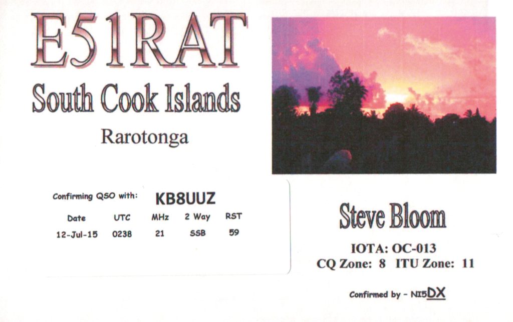
Tom, KB8UUZ, DX Engineering technical writer, worked the 2015 E51RAT activation from Rarotonga on 15M SSB.

(Image/DX Engineering) Tonga
The A31AA activation by JH3QFL from Nuku’alofa is set to run from May 14-22. You can try to make contact on 80-6M FT8.
Nuku’alofa is the capital and largest city (population 27,600) of Tonga. It is located on 100-square-mile Tongatapu, an island of around 74,600 residents, or roughly 70% of Tonga’s population. Tongatapu is one of Tonga’s 171 islands (45 inhabited) in Polynesia surrounded by Fiji, Wallis and Futuna, Samoa, New Caledonia, Vanuatu, Niue, and Kermadec.
The Pacific flying fox, locally known as peka, is Tonga’s only native land mammal. These large fruit bats are considered sacred and are protected by law in Tonga. In addition, they play an important role as pollinators and seed spreaders in native forests. Kolovai Village on Tongatapu is a popular spot to find the bats hanging in trees.
Dave, N8NB, DX Engineering technical support specialist, contacted the A35RK DXpedition to Lifuka Island (in the Ha’Apai island group) in December 2005 on 12M SSB. A35RK operated from the village of Pangai. It was on Lifuka where Captain Cook called Tonga “The Friendly Islands.”

(Image/DX Engineering) Bolivia
The multi-operator CP7DX operation from Tarija is scheduled for May 26-June 6. You can attempt to make a QSO with this 160-2M (including 60M) operation on SSB, CW, and FT8.
Tarija, population 234,000, is a city in southern Bolivia which lies in a depression in the eastern Andes known as the Central Valley of Tarija, where you’ll find 80% of the wine and singani (Bolivian brandy) grapes planted in Bolivia.
Dave, N8NB, received the QSL card below from CP4BT in March 2013. It features a llama—Bolivia’s national animal. There are more than three million llamas in Bolivia, accounting for over 60% of the world’s llama population.

(Image/DX Engineering) Visit DXEngineering.com for everything you need to upgrade your station to make sure you’re ready when entities like South Cook Islands, Tonga, and Bolivia are on the air.
You’ll find transceivers, antennas; a wide selection of amplifiers from ACOM, OM Power, Icom, and others; CW keys and paddles; headsets and speakers; and much more.
Editor’s Note: Every month, DX Engineering features QSL cards from our team members’ personal collections. To highlight upcoming DXpeditions, we’ll be displaying a few of our favorite cards along with details about what it took to make these contacts. We’re excited to share some of the special cards pulled from the thousands we’ve received over the years. We look forward to seeing your cards as well!
The post It’s All in the Cards—May the 4th Be with You on the Air! appeared first on OnAllBands.
-
ZC4RH – Cyprus SBA
Dave, G4WXJ will again be again as ZC4RH from UK Sovereign Base Area during May 25-30, 2026. QRV on 40-6m; CW, SSB, FT8, using an FT857D; 50w and dipole. QSL via DK6SP, Club Log OQRS or via LoTW.
-

The Adventure Begins in Xenia: Hamvention 2026
By Michael Kalter (W8CI) Xenia, Ohio
The World’s Greatest Amateur Radio Event Returns to Ohio
Every May, tens of thousands of radio adventurers from every corner of the globe descend on a fairground in southwest Ohio to celebrate one of humanity’s most enduring and electrifying pursuits. Hamvention® — officially the Dayton Hamvention®, though it has called Xenia home since 2017 — is the world’s largest amateur radio gathering, and the 2026 edition promises to be the most exciting yet. With the theme of Radio Adventure, this year’s event invites everyone, from the seasoned DX chaser to the curious first timer, to explore the limitless possibilities of the radio spectrum. If you have ever wondered what amateur radio is all about, or if you are a licensed ham looking to rekindle your passion and discover what’s new, Xenia, Ohio, is where you need to be on May 15, 16, and 17, 2026.
Hamvention® is not a trade show or a niche convention. It is a living, breathing community — part festival, part classroom, part marketplace, and part reunion. More than 30,000 attendees and visitors from across North America and around the world gather each year at the Greene County Fair and Expo Center, transforming a quiet Ohio city into the international capital of amateur radio for one unforgettable weekend.
What is Hamvention?
For those new to the hobby, Hamvention® is the annual convention organized by the Dayton Amateur Radio Association (DARA) and sponsored by a remarkable army of volunteers. Its roots run deep — the very first Hamvention® was held in 1952 at the Biltmore Hotel in Dayton, Ohio, making 2026 a celebration of more than seven decades of this cherished tradition. Inside the sprawling fairgrounds complex, attendees find more than 500 indoor commercial exhibits showcasing the latest equipment from major manufacturers and innovative small vendors, and more than 2,500 outdoor flea market spaces where buyers and sellers trade everything from brand-new transceivers to vintage tube radios and hard-to-find accessories. Multiple forum tracks run throughout the three days, covering topics from satellite communications and emergency preparedness to digital modes and antenna design. FCC license exams are offered on-site. Live demonstrations, prize drawings, and special event stations make every hour feel packed with possibility.
Amateur Radio in 2026: A Hobby Transformed
Amateur radio has never been more alive. As of early 2026, the FCC reports more than 736,000 active individual amateur radio licenses in the United States alone, and globally, over three million licensed operators are active across more than 160 countries. The International Amateur Radio Union (IARU), founded in Paris on April 18, 1925, now represents member societies on every inhabited continent, and the 2026 World Amateur Radio Day theme — Advancing the Spirit of Amateur Radio Through Innovation — captures the restless energy driving the community forward.
The hobby has evolved dramatically in recent years. Digital modes like FT8 rewrote what “weak signal” communication means, allowing operators to make transcontinental contacts with just a few watts of power. Experimental modes like FT2 are already being discussed in labs and forum threads. Software-defined radios (SDRs) have put sophisticated spectrum analysis tools in the hands of anyone with a laptop. Mesh networking on VHF and UHF bands is enabling hams to build their own internet-independent communication infrastructure. Machine-learning-assisted decoders are pushing the boundaries of what the human ear — or any radio — can resolve from noise. And Parks on the Air® (POTA), an activity that barely existed a decade ago, has exploded into a global phenomenon with tens of thousands of activators setting up portable stations in parks, forests, and wilderness areas around the world.
These innovations are on full display at Hamvention®. Whether you want to hold the latest Software Defined Radio in your hands, talk to an engineer designing the next generation of amateur satellites, or watch a live POTA activation from the fairgrounds, 2026’s event is where the cutting edge of the hobby comes to meet you.
A Hobby Without Age, Without Borders
One of the most remarkable things about amateur radio is how completely it transcends the boundaries that divide so much of modern life — age, nationality, background, and language. At Hamvention®, you will find ten-year-olds who just passed their Technician exam standing next to eighty-year-old Extra class operators who have been on the air for six decades. You will hear accents from Brazil, Japan, Germany, Australia, and dozens of other nations. The language of radio — the universal exchange of signal reports, call signs, and camaraderie — cuts through every barrier.
Youth engagement in amateur radio is surging. Globally, organizations like Youngsters on the Air (YOTA) run camps and contests specifically designed for licensed operators under the age of 26, drawing participants from Europe, the Americas, Africa, and Asia. The World Organization of the Scout Movement’s annual Jamboree on the Air is the largest scouting activity on earth, with roughly half a million Scouts and Guides making radio contacts each October. The World Wide Young Contesters organization brings competitive radio sport to young Europeans. And closer to home, the ARRL’s Youth on the Air camp program, held annually in North America, draws licensed young operators from across the Western Hemisphere for a week of hands-on training, cutting-edge operating, and mentorship.
At Hamvention® 2026, the ARRL Youth Rally on Saturday, May 16, is designed for students ages 11 to 21 and offers a hands-on afternoon of satellite communications, a sprint contest, a fox hunt, and the chance to make contact with a parachute-mobile station. Registration is just $20 and includes a T-shirt, badge and lanyard, reusable tote bag, and a complimentary three-day Hamvention® admission ticket. It is one of the best single investments a young ham — or a parent of a curious kid — can make.
One of the most beloved and enduring youth traditions at Hamvention® is the Radio Club of America (RCA) Youth Forum, a Saturday morning institution that has run for more than three decades. Founded and long moderated by legendary amateur radio educator Carole Perry, WB2MGP — a Fellow and Director of the Radio Club of America, past Hamvention® Ham of the Year, and recipient of the ARRL Instructor of the Year Award — the RCA Youth Forum is unlike anything else at the event. Each year, seven to eleven carefully selected young ham radio operators, some as young as nine or ten years old, take the stage to deliver polished presentations on their accomplishments, experiments, and passions within the hobby. Past presenters have spoken on topics ranging from satellite communications and high-altitude ballooning to digital radio modes, antenna homebrew, emergency preparedness, and promoting ham radio in their schools and communities around the world.
The RCA Youth Forum is open to all Hamvention® attendees and is consistently one of the most inspiring sessions of the entire weekend. The young presenters — who earn the honored title of RCA Young Achievers — receive recognition, prizes, and networking opportunities that often launch lifelong careers and friendships in radio and technology. Sponsors including Icom America have long supported the forum, providing presenters with equipment gifts and personalized recognition. Perry, who taught “Introduction to Amateur Radio” for nearly thirty years at a New York middle school, has said it best: “The Youth Forum is where we showcase our best and brightest young hams. Come support the future of our hobby and service!” For anyone who wonders whether the next generation is embracing amateur radio, an hour in the RCA Youth Forum will answer that question beyond any doubt.
Internationally, Hamvention® draws visitors from dozens of countries every year. It is the event where a ham from Poland might swap antenna-building techniques with an operator from Japan, where a British contesters share foxhunting tips with a Brazilian DXer, and where the global community of radio adventurers feels, for three days, like a single neighborhood.
At Hamvention®, the global amateur radio community becomes one neighborhood — ten-year-olds, eighty-year-olds, and everyone between them, speaking the universal language of radio.
New & Exciting Activities Showcased at Hamvention® 2026
Hamvention® is the best place in the world to discover what is happening right now in amateur radio, and 2026’s lineup reflects a hobby in the midst of a genuine renaissance. Here is a sample of what awaits:
Parks on the Air® (POTA). The POTA phenomenon has transformed how hams think about portable operating. Across multiple dedicated forums and live outdoor demonstrations, attendees can learn how to set up a field station anywhere from a city park to a remote wilderness, make contacts with stations around the world, and log activations toward awards and achievements. POTA forums at Hamvention® routinely fill large indoor spaces — a testament to how much excitement the activity has generated.Satellite Communications. AMSAT, the Radio Amateur Satellite Corporation, presents an annual forum and exhibit covering the current status of amateur satellites in orbit, upcoming launches, and how any ham with a modest handheld radio can make contacts via low-Earth orbit birds. The 2026 ARRL Youth Rally will feature live satellite communication demonstrations, giving young attendees a chance to make contact through a bird hundreds of miles overhead.
Emergency Communications. Hamvention® has always taken seriously amateur radio’s vital role in emergency preparedness. Forums and exhibits cover ARES (Amateur Radio Emergency Service), mesh networking for disaster communication, and the latest digital tools that help hams provide communications when commercial infrastructure fails. This is radio that saves lives — and Hamvention® is where the people who do this work share what they know.
Software-Defined Radio and Digital Modes. SDR technology has made it possible for anyone to explore the radio spectrum in ways previously reserved for engineers with expensive equipment. Exhibitors and forum presenters will showcase the latest SDR platforms, discuss emerging digital modes, and demonstrate how machine learning is beginning to assist in signal identification and decoding.
Special Event Station. Throughout the weekend, a special event station operates on the air from the Hamvention® grounds, giving visitors the thrill of making contacts from one of the most famous call signs in the world during the most famous radio weekend of the year.
FCC License Exams On-Site. One of Hamvention®’s most practical offerings is the opportunity to sit for your FCC amateur radio license exam right at the fairgrounds. Whether you are a first-timer going for your Technician ticket or an operator upgrading to General or Amateur Extra, volunteer examiners are on-site all three days to administer the test.
Essential Information: Hamvention® 2026
- Dates: Friday, May 15 – Sunday, May 17, 2026
- Hours: Friday & Saturday: 9:00 AM – 5:00 PM · Sunday: 9:00 AM – 1:00 PM
- Location: Greene County Fair & Expo Center, 120 Fairground Road, Xenia, Ohio 45385
- GPS / Navigation: Latitude 39.7021, Longitude -83.9420
- Gate Admission: $30 per person (one ticket covers all three days — Friday through Sunday)
- Sunday Admission: FREE — Sunday, May 17 is free admission for all attendees
- Children 12 & Under: Free with a ticketed adult, no ticket required
- Students (Jr. High – High School): Free ticket available at the Will Call window
- ARRL Youth Rally: $20 registration (Saturday, May 16) — includes 3-day admission, T-shirt, badge & tote
- Parking: Free parking included with all admission tickets
- Email: info@hamvention.org
- Website: hamvention.org
Ten Compelling Reasons to Attend Hamvention® 2026
Still on the fence? Here is why no radio enthusiast — or anyone curious about radio — should miss this event:
- The World’s Best Radio Flea Market. Over 2,500 outdoor vendor spaces offer everything from brand-new transceivers to vintage tube equipment, antennas, cables, test gear, and parts that simply do not exist anywhere else. If you are looking for something specific, the Hamvention® flea market is where you will find it.
- 500+ Indoor Exhibits. Every major manufacturer of amateur radio equipment sets up indoors, allowing you to hold, test, and compare radios, antennas, amplifiers, and accessories before you buy. Hamvention® is where new products are often announced and launched.
- Expert Forums and Presentations. Dozens of forum sessions cover everything from satellite operations and contesting to antenna theory, digital modes, emergency communications, and the science of radio propagation. Attend a morning session and come away with knowledge that would take months to accumulate from books.
- Get Your Ham License Right There. Volunteer examiners offer FCC Technician, General, and Amateur Extra class exams on-site all three days. There is no better setting to take the plunge and join the community.
- Sunday Is Free. Not sure if you want to commit to the full weekend? Show up Sunday, May 17 (9:00 AM – 1:00 PM) for zero cost. Browse the flea market, explore the exhibits, and get a taste of the world’s greatest ham radio gathering at absolutely no charge.
- Incredible Value. A $30 gate ticket buys you admission for all three days, including all forums, all exhibits, the flea market, the prize drawing, and free parking. There is no separate charge for any of the educational programming.
- A Truly International Experience. Hamvention® draws visitors from dozens of countries. You will meet hams from Japan, Germany, Brazil, Australia, Poland, and beyond. The friendships formed in the aisles of the flea market and the seats of the forum rooms are the heart of the global amateur radio family.
- Youth Programming That Inspires. The ARRL Youth Rally on Saturday is a highlight of the weekend, offering young operators and curious students a hands-on afternoon of satellite contacts, fox hunts, sprint contests, and community. Children 12 and under are always free, and student tickets through high school are also free at the gate.
- The Dayton Area Is Worth the Trip. Xenia sits between Columbus, Cincinnati, and Dayton, with easy access from three airports. While you are in the area, the National Museum of the U.S. Air Force in Dayton — the world’s largest aviation museum, open daily and completely free — is a short drive away. The Dayton Art Institute and historic Carillon Park are also nearby.
- You Will Leave Inspired. More than anything else, Hamvention® changes the way you see the hobby. The energy of 30,000 enthusiastic people who share your passion, the sight of new technology that excites your imagination, the conversation with a fellow operator from the other side of the world — these are experiences that no online purchase or YouTube video can replicate.
Come Find Your Frequency in Xenia
Amateur radio is one of the few pursuits that is simultaneously a technical discipline, a community service, a competitive sport, a scientific tool, and a deeply personal creative outlet. It spans age groups and national borders with an ease that few human endeavors can match. And three times a year, for one May weekend in Ohio, it all comes together in a way that simply has to be experienced.
Whether you are a licensed ham who has attended for thirty years or a curious newcomer who just discovered what a radio can do, Hamvention® 2026 has something for you. Come early. Stay late. Walk every aisle. Sit in on a forum. Say hello to a stranger with a call sign badge and a smile. And on Sunday morning, if you haven’t made up your mind yet, walk through the gates for free.
The adventure is waiting. And it begins in Xenia.
Dayton Hamvention® 2026
- May 15–17
- Greene County Fair & Expo Center, Xenia, Ohio
Tickets & Information
- hamvention.org
- info@hamvention.org
- Gate Price: $30 (3-day)
- Sunday: FREE
73 — Good luck, and we’ll see you on the air.
Source: Hamvention
-
FO/F6BCW – French Polynesia
[INFO] – Part of the recent TX9W DXpedition to Marquesas Islands, Didier FO/F6BCW will soon return to the airwaves from Tikehau Atoll. Earlier info and pics below. He is expected to stay in FO until mid-July. [APRIL 6 @ 2000Z] – Due to very heavy squalls and violent thunderstorms, the 30m and 40m bands are […]
-
RI1FJL – Franz Josef Land
[NEWS UPDATE] by Vasily, R7AL. I recently received a written response from the Northern Administration of Hydrometeorology and Environmental Monitoring agreeing to accommodate expedition participants at the E.T. Krenkel meteorological station on Heiss Island. This is a major milestone in expedition preparations! Accommodation will be provided on a commercial basis. There’s also a change in […]